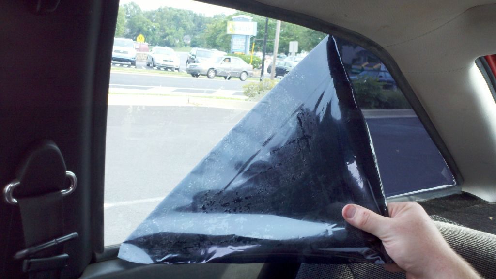
Window tint is REALLY annoying to remove. Best bet? Wait for a very hot, sunny day. This heats up the tint, and makes the adhesive softer.
The ease of tint removal really depends on what brand the tint is, and in what condition it is in. I got lucky, and this window tint peeled right off without much difficulty.
I will also detail another method that will work much more effectively on a rear window with delicate defroster lines.
This post describes how to wire your engine with the 20awg wire for Megasquirt’s wiring harness!
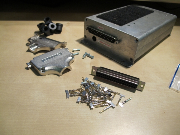
Here’s a DB-37 connector with crimp connector pins. Most megasquirt kits come with solder cup connectors WHICH ARE BAD because soldered wires = stiff corroding wires.
I ordered this connector from Newark – an electronic parts supplier. Here’s a link to part number 79K4779 – The manufacturer’s part number is SPC15175
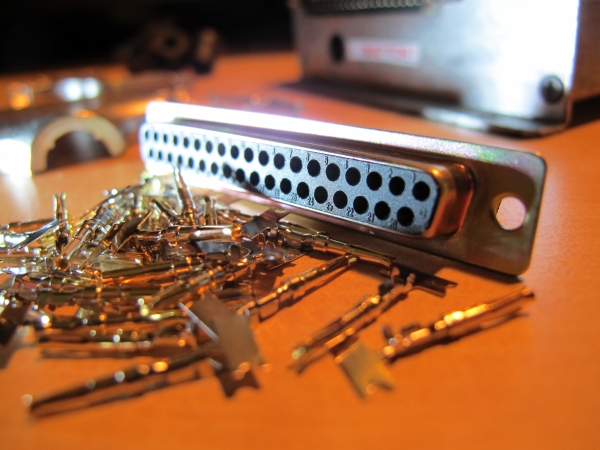
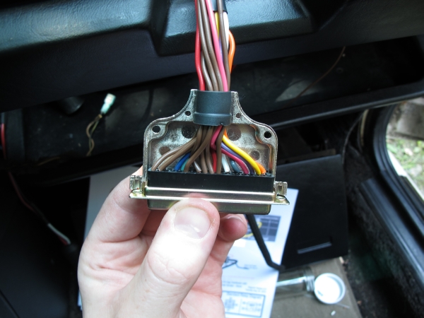
This picture shows you the pin numbers.
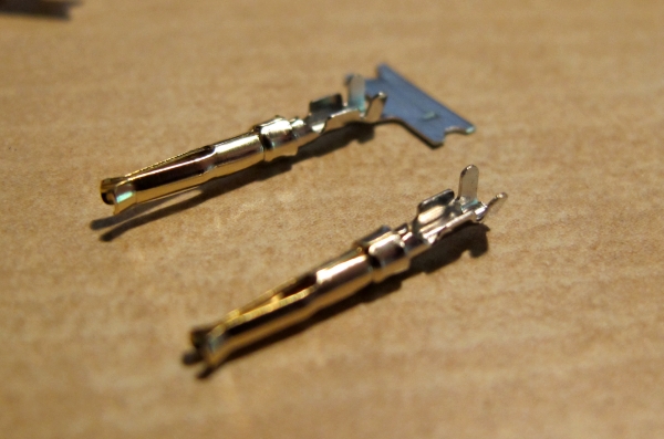
The pins come with the mass production thingy still attached. Just break it off.
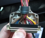
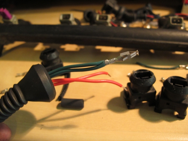
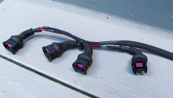
Here’s my old fuel rail wiring. I got the connectors from an early 90s Audi something or other.
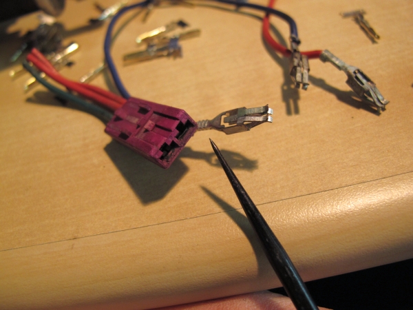
To get pins out of these, you just reach in with a sharp tool, and bend that tab down so you can pull it out from behind. This type of bosch connector has a purple removable inside. Most VWs do not have this type, but the fanch-schmancy Audis do! And you thought you were paying for just a badge.
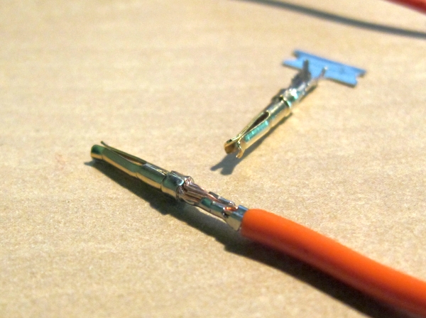
New pin crimped on. I bough these from Jim, but I’m sure there are other sources online.
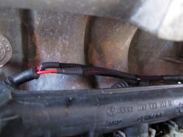
Here’s the fuel rail wiring all done.
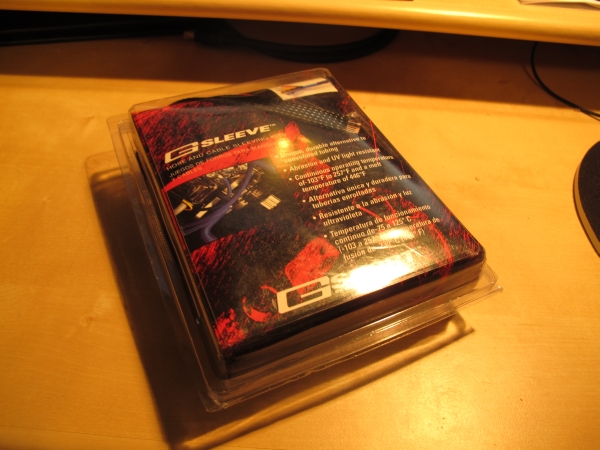
You may have noticed that cool loom there. Some people call it Techflex. But techflex is a brand name, like Xerox, it has become a generic descriptor for this type of product. The type I’m using is called G-SLEEVE! WOW! I think these are just laying about in warehouses from the street tuner era.
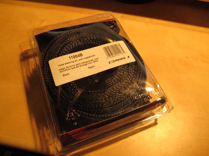
Anyway the part number is 11004B – it is made by Mr Gasket. You can order this from Advance Auto Parts if you give them the part number. It takes about 5 days because it is a direct factory order. 2023 note – this item was discontinued when I wrote this 13 years ago, so it’s no longer available.
It is very flexible. It can expand WAY bigger than it is to fit over things, connectors, crimps and such. It is permeable. It protects wires from abrasion. It keeps wires together and organized. AND IT LOOKS REALLY COOL!! So that’s why I did it with this.
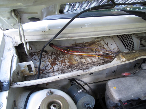
SO! We have a bunch of wires everywhere! ACK! Start in the engine bay. Use tape and electrical ties to make the wires go where they will lay. Feed the wires into the car’s interior and just let the excess go inside. Then slip on the wire looming and heat shrink to clean it up. After that, crimp or attach the sensors to the wire. When those are on, shrink the heat shrink.
My firewall hole is in the upper cowl. It’s hidden by the raintray, but VERY easy to access. DO NOT drill it too low or you’ll risk getting rainwater into your interior. By the way, you can do this hole on an A/C car too. There’s an inch of room behind the recirc duct. Drill from inside the car with the glovebox removed.
Here’s where the wiring goes into the bay, where the stock wiring did! I cut the stock grommet to make installation easy. When installed, I put the slit area facing down so you don’t see it.
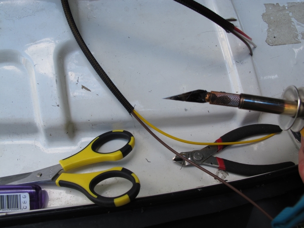
You can cut this stuff with siscors, but the best thing to do is to cut it with a heat knife, so it doesn’t fray all crazy and drive you mad while you are working with it.
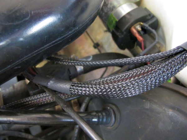
Make bigger looms that small ones feed into
Getting bigger!
Now that the engine is all done, get inside the car! Start crimping and putting the pins into your connector.
You can make the wires quite a bit easier to work with if you hit them with a heat gun for a few seconds. This makes them more flexible.
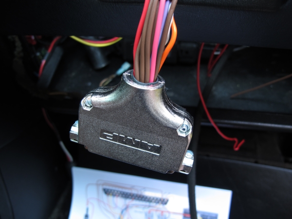
Put the connector shield’s grommet in like this, so it doesn’t fall out.
Put it together. Don’t forget to put the side screws in before you do this so you can screw it to the ECU!!
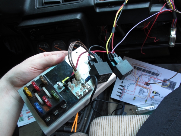
Instead of a relay board, I’m going direct. There is a VERY good reason for this. The relay board introduces MANY points of failure. Another DB connector, the terminal strip to the circuit board joints, and the terminal strip’s mechanical screw connections. The worst part is that the terminal strip on the relay board cannot handle the current that the VW fuel pump draws, so it melts.
I’m also using a small relay panel. You’ll find these all over eBay. It’s not really necessary, but I think it makes for an overall cleaner install since I have five things that need fuses.
Just look at that niftiness!
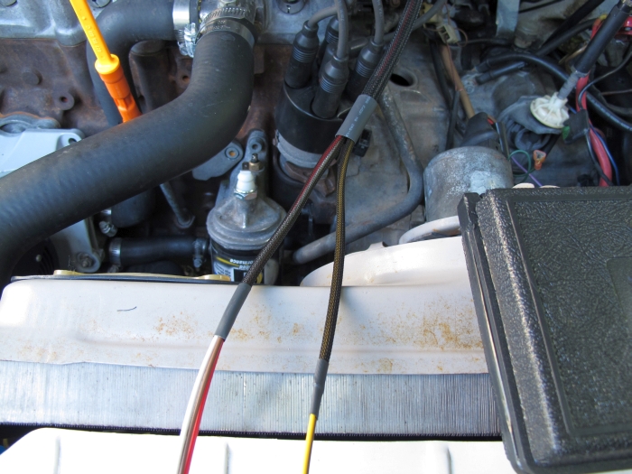
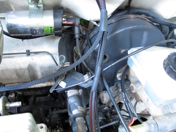
Hidden behind the fuel rail.
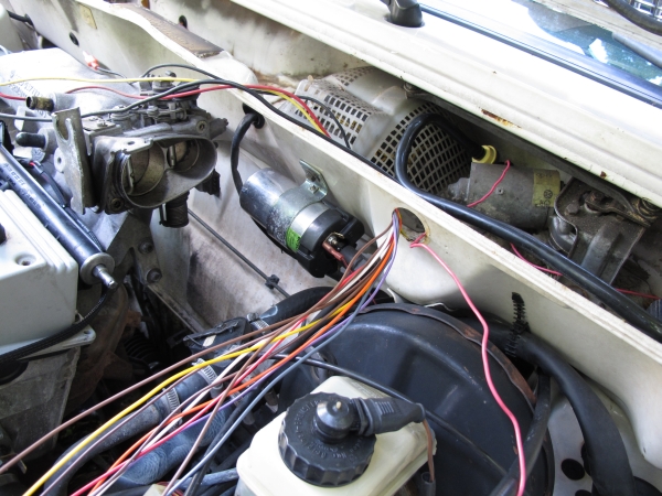
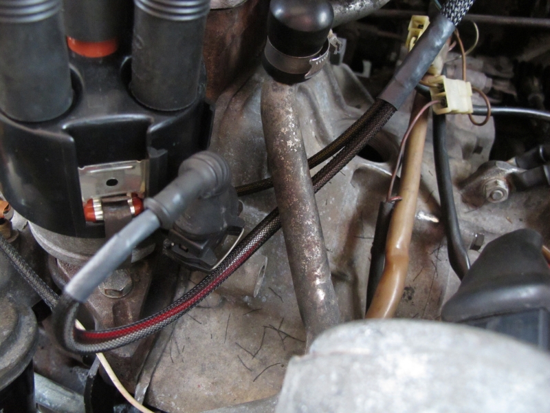
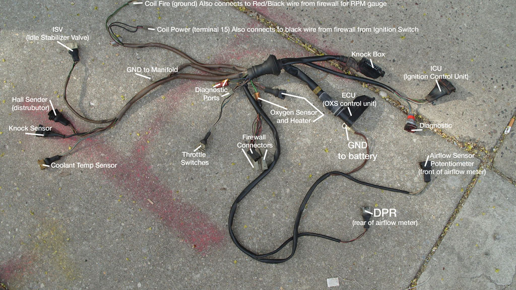
Loom going out. There’s also the wire going to the coil from the Megasquirt ECU in the background (black connector). The red/black wire with the red connector is the car’s factory RPM gauge wire that goes to the instrument cluster.
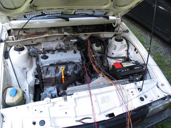
And it started right up the first try! Muahahahaah!
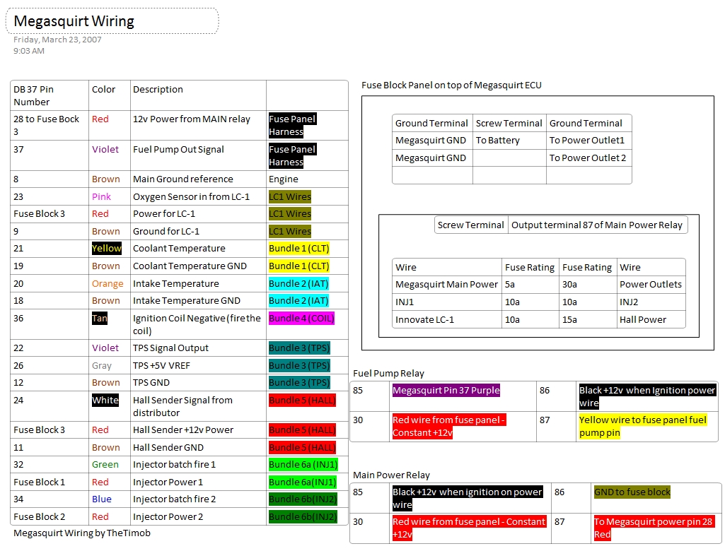
Here is my messy, but effective diagram that I used to wire my car. I know, it looks like a dang PILE of spaghetti!
The Key oddity to my wiring is that pullup resistor installed between the hall sender and a +12v wire. This can surely be installed on the Megasquirt board, but I’m not sure exactly how right now. The Megasquirt won’t detect RPM without it though. Pretty sure it is a 1k ohm 1/2 watt resistor.
Looking at it from the standpoint of words might help. Here’s a chart showing my wiring connections
This technote covers fixing broken wires in the seatback to make the seat feel like new again! If you sit down and feel the pop of a breaking support wire – this technote is for you.
First of all, I must apologize for the lack of proper photography on this post. I thought I would have more time for pics, but my pregnant wife is nesting now and she was rushing me to help her get stuff done in the nursery…
so the other day I was settling into my seat and heared a pop. then all of a sudden my seat went from ‘not-so-comfortable’ to ‘REally UNconfortable’. I have had a feeling this was coming for a while now, but I have been putting off the repairs until it got ‘really bad’.
anyway. these seats have quite the little skeleton of wires and springs inside of them and they can break in all sorts of different places.
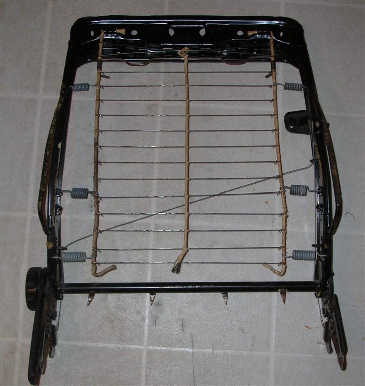
here is a pic with some areas colored for refence:
<picture>
Seatback Image, Click to Enlarge
the pink horizontal lines are very thin wires crossing the width of the seat connecting together the two heavy gauge spring steel ‘wires’ that I marked in green. these two wires are held tight by 3 springs on each side. (blue arrows)
so when I first got the rocco, the drivers side seat was a bit sloppy. some of the ‘pink’ wires had broken and were actually poking out of the back of the seat. I repaired it by taking it all apart and sourcing some used wires from a donor seat. the problem was that they werent all the same length and my seat was still quite uncomfortable.
up until now, I have just been dealing with the lumpy uncomfortable seat, when it broke again I knew it was time to do something about it.
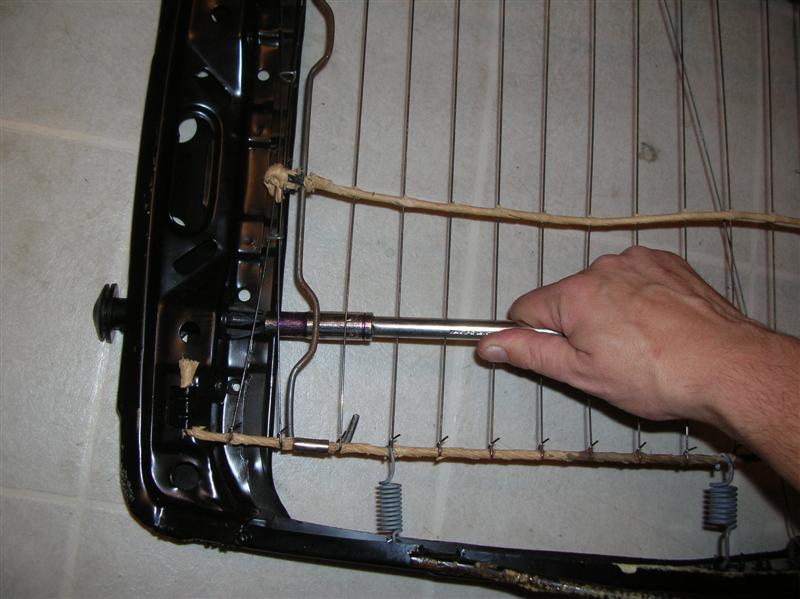
in the picture the red circle is drawn around the spring that gets the most abuse. it is a much heavier gauge than the other two, and what happens with this spring is that it slowly wears a notch in the ‘green’ wire and creates a weak point. when I squeazed into the seat the other day, I finally caused that spring to actually break the ‘green’ wire at the wear point, and all support from the seat back was lost.
the solution: I took the seat back out of the car and took it all apart. I seperated all of the hogs ring staples with a pair of needle nose plyers. I didnt have to remove the head rest, but I did have to peel back all of the vynil covering the seat to properly get at all of the innards.
I picked up some heavy gauge metal rod from the shop. the original wire is very hard to bend. the replacement part was a much heavier gauge, but still easier to bend than the stock part. you might be able to get away with using two or three lengths of coat hanger wire to get the firmness of the OEM part. just stay away from brass as it will get brittle far sooner than steel.
next I had to remove the old wire, and unfasten every one of the ‘pink’ wires attached to it, as well as the springs, a clip and so on.
the old wire is covered with a paper wrapping twisted all around it. this keeps the springs and ‘pink’ wires from moving around on it. I wrapped my new wire with rubber stretch tape.
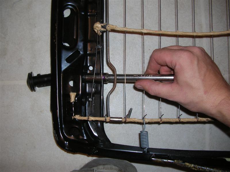
then I started reassembling it and took extra special care to make all of the “pink” wires to have the same tention on them. I had to do some fine tuning, but once the majority of these wires were on, I attached all of the springs and could easily tell which ones of these wires was too loose. Hint: if you can wiggle the wire, its too loose.
with all my wires correctly tightend and all the rest of the parts in place, I pulled the skin back in place and clamped the 20 or so hogs rings(staples) in place to keep the skin where it belongs.
So then I reinstalled it back in the car and smiled as sat down to the most comfortable scirocco seat I have ever been in.
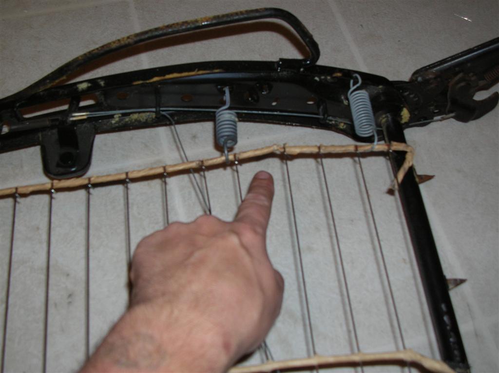
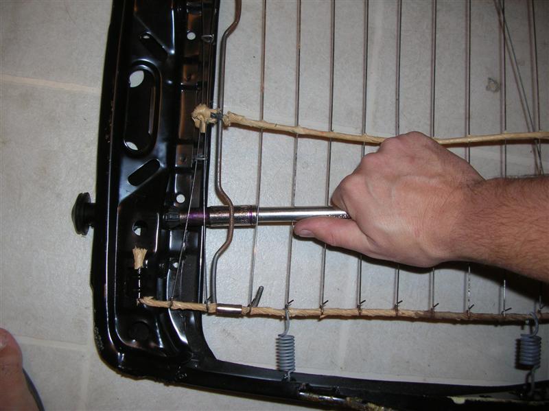
Seatback Frame
my pictures are really out of focus, but if you look hard you can se that there are three different places where you can attach that spring. this set of springs was not broken yet but they were working on it. so I moved the springs up to the top spring as a preventative measure.
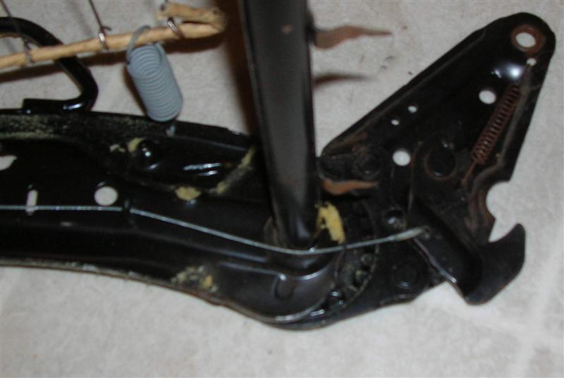
Frame wear point
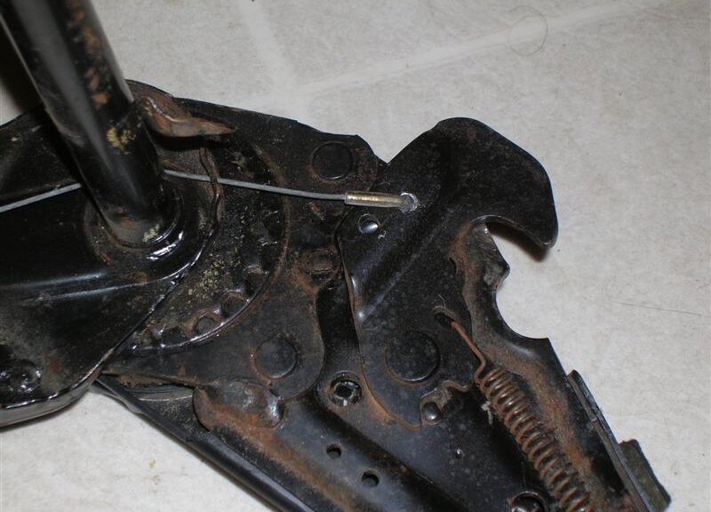
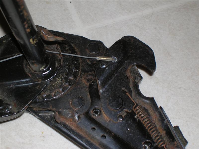
Release cable issues. I would say that the number one issue with the rocco seat release is due to streching cables. the next would probably be breakage of the plastic routing guides followed by actual breakage of the cables. I got this set of seats used from a friend, and they were very stubborn when told to tip forward. I could fight with it for a while and get them to release, but most of the time I had to reach down and lift the lock to get them to go. the problem was that the long release cable had stretched over time, and the short one was hitting the stopper before the other one had a chance to open up enough to unlock.
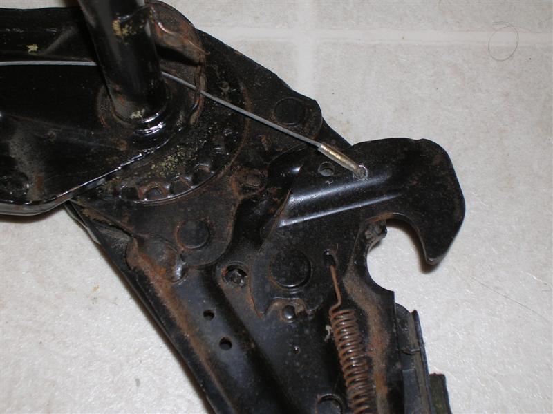
here are some pics to explain wheat Im talking about. this one shows the short side. I have the release lever lifted all the way up to show that this side is fully opened.
Cable
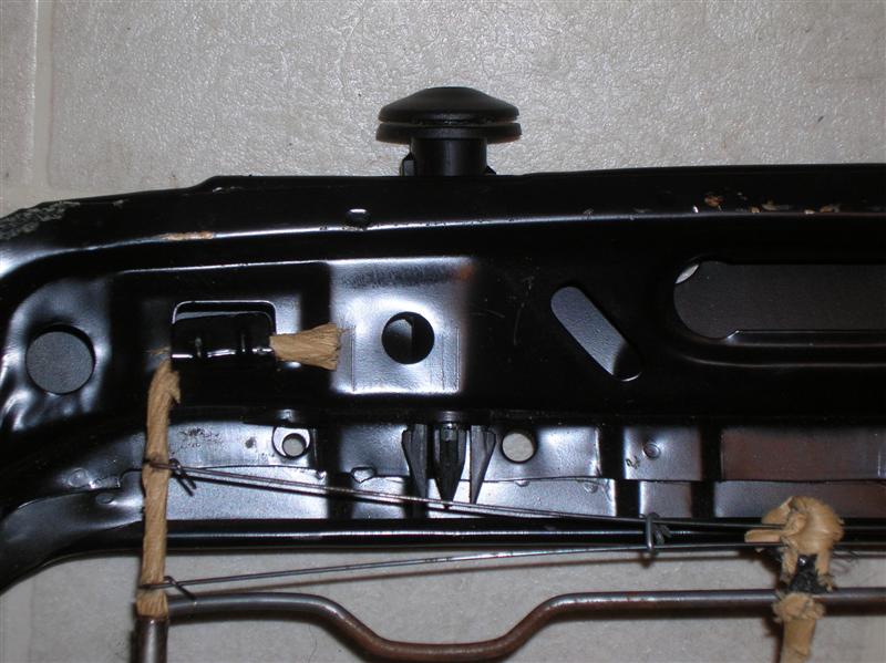
on the other side, the lock was not fully open, in fact it had another quarter of an inch to go before it would release. I dont have pics of that. anyway, I drilled a new hole to fit the cable through that would take up that extra quarter of an inch needed to open it all the way.
notice the old hole just to the left of the one the cables in.
Cable with new hole
now when I lift the release lever both sides hit the stopper and are fully opened.
Solved
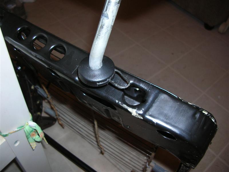
A word about seat disassembly: the head rest is mounted to the seat by these two plastic tubesand held in with pins. taking the pins out is easy enough, but getting the skin off the seat to do major repairs requires removing these plastic tubes, and that can be a real pain. Ive taken some pics of my secret to getting those plastic tubes out of the seats.
My pics are of a seat thats already apart, so you can better see the part you will be fighting with. with the skin and the cushion stuff on the frame you will not be able to see what you are doing in there, so you will need toknow what you are feeling for.
First. the offending beast.
Annoying Clips
and out of order, removing the pin that holds the headrest in place.
Remove Pin
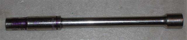
my secret weapon is a 10mm socket on an extention for leverage.
Socket
you need to get all the tips of the plastic thing inside the 10mm socket.
Surround tips in Socket
now push like hell and wiggle that back and forth. if you stick a finger in there to assist you might get stung. so be careful the edges can be sharp.
Push and Fight!
eventually you will be rewarded with a satisfying POP! 😀
Pop!
now repeat this for the other side and get yourself a beer.
Clips!
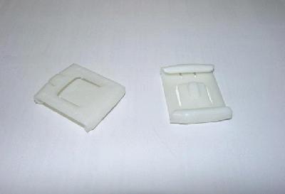
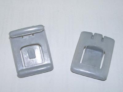
Doe your seat rock about? You’ll need the plastic guides that keep the seat base from jiggling round in the base…
in which case, you need two, one for each side of the seat. the outers are 171881213b
the inners are 191881213909
you will notice there isn’t a heck of a lot of difference between these two parts. the only noticeable difference is the little tab sticking out of the gray one. the white ones are about 5 times as much as the gray ones. being cheap, I took a couple gray ones and shaved the tab off and used them as whites
Inner Clips
Outer Clips
Here’s some pictures of Jonny’s re-upholstered seats!
So, for some reason, there’s not much documentation on what this actually means!! Well- we discovered that this problem can create all kinds of hell if you don’t know much about it. Click this pic to enlarge for a full explanation… I’ll add more to this VERY soon.
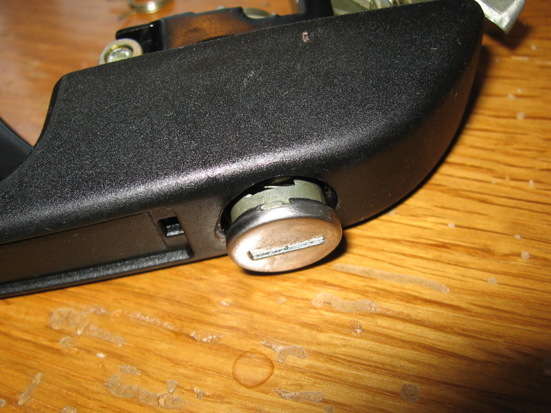
This is how to swap a lock cylinder from one lock housing to another. Mine had a couple of stripped screws, making the car honk when the highbeams were turned on. This technote also shows how to remove the steering wheel, turn signal, and wiper switches.
You know those numbers on the back of switches, relays, panels and more? They are the DIN standard terminal numbers. They can help you troubleshoot electrical problems. For example, Terminal 15 is ignition on power. Read on for the big list!
Special thanks to Nick (vwpieces on VWVortex.com) for this information!
Terminal Designations (Excerpts from DIN Standard 72 552) The terminal designations do not identify the conductors, because device with different terminal designations can be connected at the two ends of each conductor. If the number of terminal designations is not sufficient (multiple-contact connections), the terminals are consecutively numbered using numbers or letters whose representations of specific functions are not standardized.
Ignition
1 Ignition coil, ignition distributor, low voltage 1a To ignition contact breaker I 1b To ignition contact breaker II 2 Short-circuit terminal (magneto ignition) 4 Ignition coil, ignition distributor, high voltage 4a From ignition coil I, terminal 4 4b From ignition coil II, terminal 4 15 Switched + downstream of battery (output of ignition switch) 15a Output at dropping resistor to ignition coil and starter
Glow Plug and Starter Switch (Diesel)
17 Start 19 Preheat
Battery
30 Direct battery positive 30a Direct battery II positive (dual battery system) 31 Direct battery negative (Ground) 31a Return line to negative terminal of battery II 31b Return to negative battery terminal via switch or relay 31c Return line to negative terminal of battery I
Electric Motors
32 Return line (Polarity reversal possible at terminals 32-33) 33 Main terminal connection (Polarity reversal possible at terminals 32-33) 33a Self-parking switch-off 33b Shunt field 33f For second lower-speed range 33g For third lower-speed range 33h For fourth lower-speed range 33L Counterclockwise rotation 33R Clockwise rotation
Starter
45 Separate starter relay output; starter input (main current) 45a Output, starter I Input, starters I and II (Two-starter parallel operation) 45b Output, starter II (Two-starter parallel operation) 48 Terminal on starter and on start-repeating relay for monitoring starting procedure
TURN SIGNAL FLASHER
49 Input 49a Output 49b Output, second turn-signal circuit 49c Output, third turn-signal circuit
STARTER
50 Starter control (direct) 50a Output for starter control (Series-parallel battery switch) 50b Starter control with parallel operation of two starters with sequential control 50c Input at starting relay for starter I (Starting relay for sequential control of the engagement current during parallel operation of two starters) 50d Input at starting relay for starter I (Starting relay for sequential control of the engagement current during parallel operation of two starters) 50e Input, Start-locking relay 50f Output, Start-locking relay 50g Input, Start-repeating relay 50h Output, Start-repeating relay
ALTERNATOR
51 DC voltage at rectifier 51e DC voltage at rectifier with choke coil for daytime driving
TRAILER SIGNALS
52 Signals from trailer to towing vehicle, general
WIPER MOTOR
53 Wiper motor, input (+) 53a Wiper (+), self-parking switch-off 53b Wiper (shunt winding) 53c Electric windshield-washer pump 53e Wiper (brake winding) 53i Wiper motor with permanent magnet and third brush (for higher speed)
TRAILER SIGNAL
54 For lamp combinations and trailer plug connections
TRAILER STOP LAMP
54g Pneumatic valve for additional retarding brake, electromagnetically actuated
LIGHTING
55 Fog lamps 56 Headlamp 56a High beam, high-beam indicator lamp 56b Low beam 56d Headlamp-flasher contact 57 Side-marker lamp: motorcycles, mopeds. Abroad also cars, trucks, etc. 57a Parking lamp 57L Parking lamp, left 57R Parking lamp, right 58 Side-marker lamps, tail lamps, license-plate lamps and instrument-panel lamps 58b Tail-lamp changeover for single-axle tractors 58c Trailer plug-and-receptacle assembly for single-conductor tail-lamp cable with fuse in trailer 58d Variable-intensity instrument-panel lamp, tail-lamp and side-marker lamp 58L Side-marker lamp, left 58R Side-marker lamp, right; license-plate lamp
85 Output, actuator (end of winding to ground or negative) 86 Start of winding 86a Start of winding or 1st winding 86b Winding tap or 2nd winding Relay contact for break and changeover contacts 87 Input 87a 1st output (break side) 87b 2nd output 87c 3rd output 87z 1st input 87y 2nd input 87x 3rd input Relay contact for make contact 88 Input Relay contact for make and changeover contacts (make side) 88a 1st output 88b 2nd output 88c 3rd output Relay contact for make contact 88z 1st input 88y 2nd input 88x 3rd input
ALTERNATOR and VOLTAGE REGULATOR GENERATOR and GENERATOR REGULATOR
B+ Battery positive B- Battery negative D+ Dynamo postive D- Dynamo negative DF Dynamo field DF1 Dynamo field 1 DF2 Dynamo field 2 Alternator with separate rectifier J Excitation winding positive K Excitation winding negative Mp Center point terminal U,V,W Alternator terminals (three-phase designations from IEC 60034-8 ) X,Y,Z Generator terminals
DIRECTION INDICATOR (turn-signal flasher)
C First indicator lamp C0 Main terminal connection for separate indicator circuits actuated by the turn-signal switch C2 Second indicator lamp C3 Third indicator lamp (e.g., when towing two trailers) L Turn-signal lamps, left R Turn-signal lamps, right
This is just a quick tip on Exhaust Studs for the head. These are better than the stock ones, they are made of better metal, and they have a torx heat to make removal much easier. These are much less likely to break than the stock ones.
Many earlier cars still use a points-type ignition. While this has been replaced by transistorized ignition, there are good reasons to keep it original. If you are doing a full restoration, of if you just trust your breaker-points car that will survive a nuclear explosion, this technote is all about points!
This technote is still in it’s beta version. More will be added very soon!!
ATS Technotes + Timbo's Technotes. An archive of tech procedures for fixing early watercooled VWs from 1975-1992 with a focus on the VW Scirocco Mk1 and Mk2.


 Many earlier cars still use a points-type ignition. While this has been replaced by transistorized ignition, there are good reasons to keep it original. If you are doing a full restoration, of if you just trust your breaker-points car that will survive a nuclear explosion, this technote is all about points!