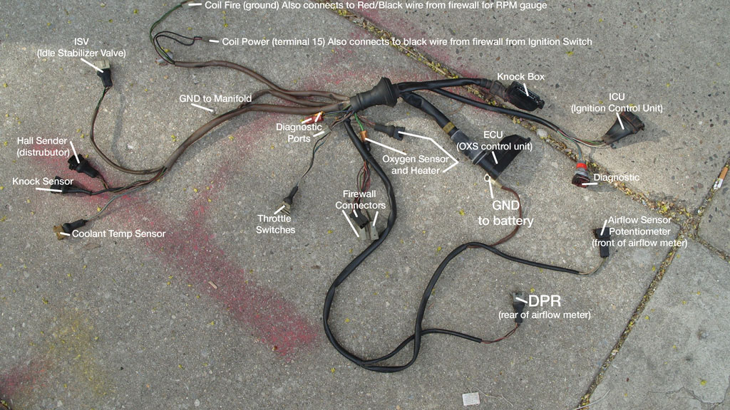
This quick technote details the CIS-E wiring harness, as found in a 1987 VW Scirocco. This should be similar for any 1.8L 16v.
This picture shows the whole harness with everything labeled.

This quick technote details the CIS-E wiring harness, as found in a 1987 VW Scirocco. This should be similar for any 1.8L 16v.
This picture shows the whole harness with everything labeled.

You know those numbers on the back of switches, relays, panels and more? They are the DIN standard terminal numbers. They can help you troubleshoot electrical problems. For example, Terminal 15 is ignition on power. Read on for the big list!
Special thanks to Nick (vwpieces on VWVortex.com) for this information!
Terminal Designations (Excerpts from DIN Standard 72 552) The terminal designations do not identify the conductors, because device with different terminal designations can be connected at the two ends of each conductor. If the number of terminal designations is not sufficient (multiple-contact connections), the terminals are consecutively numbered using numbers or letters whose representations of specific functions are not standardized.
1 Ignition coil, ignition distributor, low voltage
1a To ignition contact breaker I
1b To ignition contact breaker II
2 Short-circuit terminal (magneto ignition)
4 Ignition coil, ignition distributor, high voltage
4a From ignition coil I, terminal 4
4b From ignition coil II, terminal 4
15 Switched + downstream of battery (output of ignition switch)
15a Output at dropping resistor to ignition coil and starter
17 Start
19 Preheat
30 Direct battery positive
30a Direct battery II positive (dual battery system)
31 Direct battery negative (Ground)
31a Return line to negative terminal of battery II
31b Return to negative battery terminal via switch or relay
31c Return line to negative terminal of battery I
32 Return line (Polarity reversal possible at terminals 32-33)
33 Main terminal connection (Polarity reversal possible at terminals 32-33)
33a Self-parking switch-off
33b Shunt field
33f For second lower-speed range
33g For third lower-speed range
33h For fourth lower-speed range
33L Counterclockwise rotation
33R Clockwise rotation
45 Separate starter relay output; starter input (main current)
45a Output, starter I Input, starters I and II (Two-starter parallel operation)
45b Output, starter II (Two-starter parallel operation)
48 Terminal on starter and on start-repeating relay for monitoring starting procedure
49 Input
49a Output
49b Output, second turn-signal circuit
49c Output, third turn-signal circuit
50 Starter control (direct)
50a Output for starter control (Series-parallel battery switch)
50b Starter control with parallel operation of two starters with sequential control
50c Input at starting relay for starter I (Starting relay for sequential control of the engagement current during parallel operation of two
starters)
50d Input at starting relay for starter I (Starting relay for sequential control of the engagement current during parallel operation of two
starters)
50e Input, Start-locking relay
50f Output, Start-locking relay
50g Input, Start-repeating relay
50h Output, Start-repeating relay
51 DC voltage at rectifier
51e DC voltage at rectifier with choke coil for daytime driving
52 Signals from trailer to towing vehicle, general
53 Wiper motor, input (+)
53a Wiper (+), self-parking switch-off
53b Wiper (shunt winding)
53c Electric windshield-washer pump
53e Wiper (brake winding)
53i Wiper motor with permanent magnet and third brush (for higher speed)
54 For lamp combinations and trailer plug connections
54g Pneumatic valve for additional retarding brake, electromagnetically actuated
55 Fog lamps
56 Headlamp
56a High beam, high-beam indicator lamp
56b Low beam
56d Headlamp-flasher contact
57 Side-marker lamp: motorcycles, mopeds. Abroad also cars, trucks, etc.
57a Parking lamp
57L Parking lamp, left
57R Parking lamp, right
58 Side-marker lamps, tail lamps, license-plate lamps and instrument-panel lamps
58b Tail-lamp changeover for single-axle tractors
58c Trailer plug-and-receptacle assembly for single-conductor tail-lamp cable with fuse in trailer
58d Variable-intensity instrument-panel lamp, tail-lamp and side-marker
lamp
58L Side-marker lamp, left
58R Side-marker lamp, right; license-plate lamp
59 AC voltage, output, rectifier, input
59a Charging armature, output
59b Tail-lamp armature, output
59c Stop-lamp armature, output
61 Alternator charge-indicator lamp
71 Input
71a Output to horns 1 & 2, low
71b Output to horns 1 & 2, high
72 Alarm switch (rotating beacon)
75 Radio, cigarette lighter
76 Speaker
77 Door-valve control
Break-contact and changeover switches
81 Input
81a 1st output, break side
81b 2nd output, break side
Make-contact switches
82 Input
82a 1st output
82b 2nd output
82z 1st input
82y 2nd input
Multiple-position switches
83 Input
83a Output, position 1
83b Output, position 2
83L Output, left-hand position
83R Output, right-hand position
84 Input, actuator and relay contact
84a Output, actuator
84b Output, relay contact
85 Output, actuator (end of winding to ground or negative)
86 Start of winding
86a Start of winding or 1st winding
86b Winding tap or 2nd winding
Relay contact for break and changeover contacts
87 Input
87a 1st output (break side)
87b 2nd output
87c 3rd output
87z 1st input
87y 2nd input
87x 3rd input
Relay contact for make contact
88 Input
Relay contact for make and changeover contacts (make side)
88a 1st output
88b 2nd output
88c 3rd output
Relay contact for make contact
88z 1st input
88y 2nd input
88x 3rd input
B+ Battery positive
B- Battery negative
D+ Dynamo postive
D- Dynamo negative
DF Dynamo field
DF1 Dynamo field 1
DF2 Dynamo field 2
Alternator with separate rectifier
J Excitation winding positive
K Excitation winding negative
Mp Center point terminal
U,V,W Alternator terminals (three-phase designations from IEC 60034-8 )
X,Y,Z Generator terminals
C First indicator lamp
C0 Main terminal
connection for separate indicator circuits actuated
by the turn-signal switch
C2 Second indicator lamp
C3 Third indicator lamp (e.g., when towing two trailers)
L Turn-signal lamps, left
R Turn-signal lamps, right
Reference: Bosch Automotive Handbook, 3rd Edition
This technote will be all about the Megasquirt relay board. I have just ordered one, and I will install it after the MD/PA Megasquirt Tech weekend GTG.
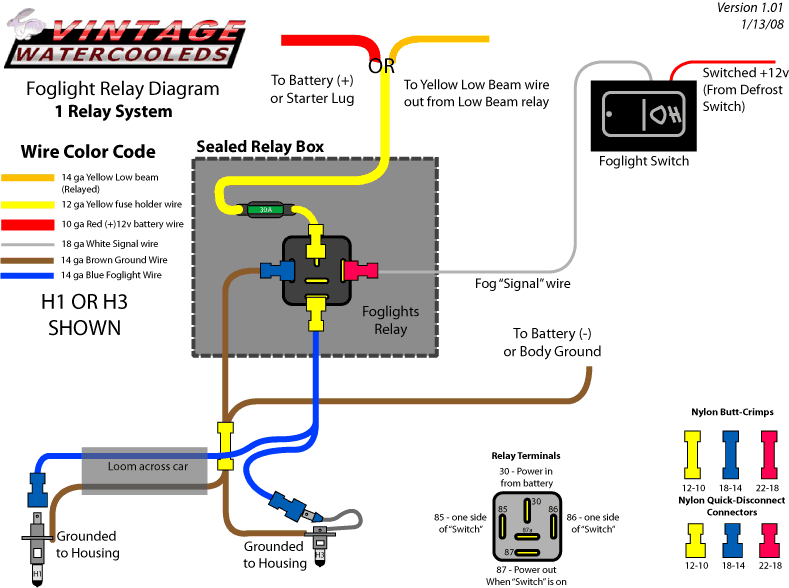
This quick and easy technote will show you how to wire fog lights into your car. You also have the option of wiring them so that they only come on with the low beams, in case your state inspection requires that.
Just take a look at the diagram – it’s pretty straightforward. Use 14 Gauge Automotive Primary wire. For the power wire, consider 12 gauge.

This article is about the Throttle Position Sensor on the throttle body, and why you may not need it at all.
Why relay your headlights? What is a relay even? All of your questions are answered right here!

Relays make your headlights brighter by directly connecting them to the battery with a sort of remote switch called a Relay. It is a required modification for Scirocco II with European lights, the wires are different, and the wattages are higher.
US headlights on a lot of our cars have very low wattage, sometimes as low as 35watts. European headlights with H4 bulbs start out at 55 watts and can go above 120 watts per bulb. Stock wiring cannot handle this extra load. The way the headlight system works in a VW is for the power to go from the Battery to the fuse panel, through the load reduction relay, then up to the headlight switch, then all the way back out to the headlights.
A headlight relays system acts as a remotely controlled switch. Now the power runs from the battery to the relay to the headlight – a very short distance. The relay is told to turn on by the stock wiring. A relay uses far less current than the headlights do, taking a load off of your electrical system, and making your switch last longer.
Continue reading Headlight Relays